3-axis milling
A starting point for pockets, profiles and other features accessible from a single setup.
Custom milled and turned parts for prototypes, fixtures and production. Share your drawings for a review of geometry, material and tolerances.
Upload your drawings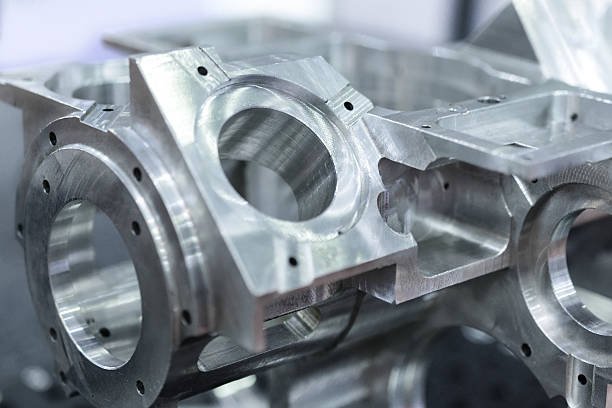
We review each drawing to confirm the setup, tool access and inspection requirements.
A starting point for pockets, profiles and other features accessible from a single setup.
Suitable for multi-sided features and complex surfaces. The setup depends on tool access and part geometry.
For round parts such as shafts, spacers and bushings, including threaded or grooved features.
Use these figures for preliminary planning. We confirm the usable size, tolerances and lead time for your part when we quote.
| Specification | Planning reference |
|---|---|
| Milling envelope | Up to 1,524 × 762 × 508 mm |
| Turning diameter | Up to Ø508 mm |
| Turning length | Up to 2,032 mm |
| General dimensional tolerance | ±0.127 mm |
| Tighter dimensional tolerance | Down to ±0.025 mm on suitable features with additional processing |
The milling envelope depends on the machine and setup. Maximum turning diameter and length are separate limits. Mark any critical fits or tolerances on your drawing.
Use these guidelines to check your drawing before requesting a quote. Feasible dimensions depend on the material, geometry and process selected for your part.
Leave an inside radius where the part allows it. Tight corners can require smaller tools and additional setups. Mark any corners that must stay sharp.
Flag deep, narrow pockets on the drawing so we can check tool access and reach. Include any critical bottom or sidewall finish requirements.
Show the diameter, depth and whether each hole is blind or through. That helps us review drilling access and chip removal.
Choose a grade or tell us what the part needs to withstand.
See material optionsRequest an as-machined finish, bead blasting, anodizing or powder coating. Mark any surfaces that must be masked or held to a roughness specification.
See our review and inspection process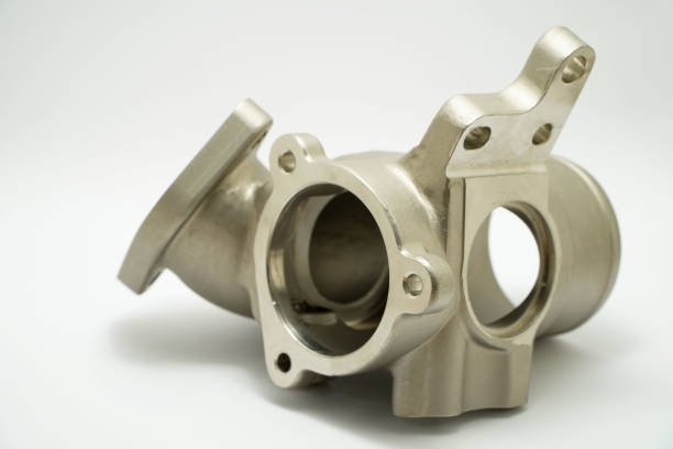
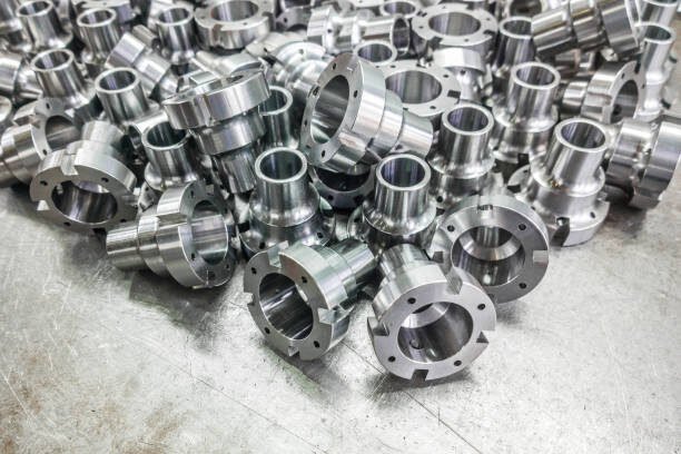
This example shows flanged steel parts with a central bore, a stepped outside diameter and mounting holes. Use a dimensioned drawing to identify the surfaces that locate or mate with the rest of the assembly.
Send a STEP model and a dimensioned PDF when available. Include your material, quantity and finish requirements.
Mark the critical dimensions on your drawing. We check achievable tolerances against the material, geometry and inspection needs before quoting.
Yes. Include the quantity you need now and any expected follow-on volume so we can review both.
Send your drawing, quantity and any critical requirements for review.